Scratch Stock Molding

rchampagne

Well-known member
I am in the process of building a highboy and the time has come for me to make the upper case moldings.  This is a Newport highboy with a bonnet top.  The molding will look like the attached profile.  I made a practice piece and cut away much of the waste with saw kerfs on the table saw.  Now I would like to finish the profile with scratch stocks.  I will make the side pieces first, then move on to the curved gooseneck.  I am assuming that the best way to do it would be to break down the overall profile into sections, ie, the ogee at the top, the cove, and the astragal at the bottom, and make seperate scratch stocks for the various components.  Is this the best way?  It seems like scratching the whole profile at once would be very difficult. 
Thanks,
Rob
 

Attachments

  • th_Moldingprofile.jpg
    th_Moldingprofile.jpg
    3.9 KB · Views: 76
I would break the the moulding down into several stages. Small scratch stock blades won't chatter as much as large ones.

I would take numerous light passes and after the initial pass, observe any changes in grain direction and any resultant tearing. If the tear-out is significant, you might want to consider solidifying the wood with size or shellac before proceeding.
 
I've done it both ways and concluded, incorrectly I'm sure, that it was easier for me to do it with a single whole profile scraper mounted in a custom scratch stock.  This allowed the fence of the scratch stock, which is modified for curves, to register against the top edge of the moulding, which is thick enough.  If you do multiple tools, for the lower bead, fillet, and cove you'll find you want to register the scratch stock fence against the bottom edge of the gooseneck, which lacks the meat for the job and must be blocked up.  Registering the scratch stock against the upper edge to do the bead fillet and cove would lead you to making the wooden blade holding area of the scratch stock sort of follow the moulding profile so as to support the cutting steel which has to drop about an inch from the proudest part of the moulding.  
For me, accuracy was best achieved using power tools.  It's very impressive to see how well the originals were done.  The inflection point of the gooseneck is sensitive to small errors.  My best outcomes were to attach the rough sawn out blank to a carefully shaped pattern and using either a shaper or a router table with a tall pattern bit shape the outsides perfect.  I then use a router with a custom, 2 point fence and a straight bit to set in the rabbets, fillets, and other prominent moulding lines.  These remain inviolate.  The router can then be used in a couple of passes to take some more wood out of the cove, where most removal is required.  Then gouges to rough the profile, always staying clear of the rabbet lines.  Scratch stock with carefully prepared cutter.
The question of how you use the inevitable waste at either end comes up also.  You want it to a minimum because you have to run it a little long, but the longer the waste, the wider the blank required.  Heck, if you ran a few inches of straight, or level, moulding at either end of the blank while using the above described method, you'd have the upper returns made also.  Never tried that though.  I set it up with enough waste on either end to lay out and precut a level section at either end.  The provides assurance with mitering later on.  Make sure you lay out the ends of the blank.  Gluing white paper with the profile drawn on helps immensely.  Mould accurately all the way through the waste at either end that you'll be mitering off later.
 
All good advice so far. Most of it can be carved and then cleaned up with scratch stocks. It is counterintuitive, to me anyway, but while making a Newport Secretary, I was advised to first cut the straight side sections, miter them, then miter the gooseneck and that allows you to mark the pattern on the end of the gooseneck. Then carve and scratch it out. You got to end up there so might as well get it done. Otherwise, you carve the gooseneck and might waste a lot if time if you botch the miter angle while trying to cut a curved piece.

John
 
That was the advice Al Breed had on his website, so that was my plan.  JD, I took your comment to heart and made a scraper that would cut the entire profile.  I tried it out on my straight stock and indeed, it does work quite nicely.  I'm sure it will be a bit more of a challenge on the curved sections.  How often do you guys renew the edge on a scratch stock?
Thanks,
Rob
 
On renewal, I don't renew as often as I should.  This doesn't seem to affect the quality of the moulding so much, per se, as it does affect my ability to produce the moulding cleanly.  A quick flattening and swipe with a pointed burnisher should be all you need to renew the profile.
My biggest difficulties in doing the whole profile scraper for curved mouldings are 1.) keeping it radial to the section, and 2.) keeping it scraping evenly across the whole profile.
I haven't done this type of crown for many years (6 or so), but have recently embarked on a secretary and am thus keen to learn from your experience as well as that of the rest of good and generous folks here.  The good news is that the first time is intimidating and thus takes a long time.  After that, you'll rock and roll through these.

As an aside, I found that the first time I did it, it all turned out well, but I was very careful and exceeding slow.  The second time I did it, I thought that I oughta be able to just blast through everything since I knew how.  It didn't turn out as well as the first time, but you can't tell by looking at it.  Anybody else ever have that experience?

JD

JD
 
Rob and others- One trick in getting the moldings done easily is to carve as much as you can and thus reduce the amount of scraping you need to do. Another is to use a scraper that isn't too thick. You want the scraper to flex a little to store some energy and not chatter. Thicker blades are definitely a liability when it comes to scratch stocks, in my opinion.
Sometimes I use the scrapers off the grinder, but eventually I'll file them and put a burr on just like a regular cabinet scraper. This will give a nice clean finish and eliminate most sanding, which I detest.........Al
 
JD,
You're not kidding about these things taking a long time.  I just spent a few hours scratching my head, and I have scaled drawings to look at.  In another post you talk about inflecting the line in your drawing.  This is the part that seems most confusing to me.  I'm still surprised at how a profile changes when you miter it.  Hopefully I won't make too much firewood.  I've got one curved blank cut out and will try routing out the waste tomorrow, hopefully. 
Al, I scraped the whole straight molding (side returns) with a scratch stock with no burr.  This was how some folks used a scratch stock in some videos I watched.  You get better results with a burr? 
Rob,
Still scratching my head. 
 
Rob- Sometimes they work fine right from the grinder or file, but if there are ragged spots I'll use a finer file to clean the edge or turn a burr with a burnisher-Al
 
Back to the question regarding whether the scraper should be the whole profile or whether the profile should be broken  up into several different scrapers. My experience is that the most difficult part is the bead at the bottom and I do that with a seperate scraper, a different one for the cove, etc. I also find with multiple scrapers it's easier to clean up at the margins of the different shapes. It  would seem to me that it would be very difficult to keep a scraper with the whole profile registered perpendicular to the arc of the curved molding.
Any comments from Al and others?

Howard Steier
 
I carve each shape and then use a separate scraper for each profile.  If you carve one of the profiles too deep you can then use the separate scraper to blend it all together.

Dennis Bork
Antiquity Period Designs, Ltd.
 
Howard- I make separate scrapers for the exact reason you mentioned: it's hard to keep everything in line and scraping over the width of a big profile-Al
 
Rob:

How's it going with the gooseneck?
In answer to your question about my remark about the inflection point, I should say that I approach this problem initially from a geometrical point of view.  I measured a Townsend piece, traced it, fondled it, etc. and studied the results for a long time.  I convinced myself that the old timers used geometrical principles to lay out these features because the cases are often of different width, and thus would require new patterns for each different size case.  I believe I found the geometry they used, the scheme for locating the centers of the arcs and laid out the entire bonnet this way, using a compass.  The lower, upcurved part using a different center than the upper half.  All lines made this way must meet at the inflection point where the moulding changes curvature.  Drafting this needs to be done very carefully.  The template formed from the drawing must then be shaped to fair curves, irrespective of any inaccuracies in the drawing.  In shaping the curves of the patterns, I found I had to spend the most time getting the inflection point just right, because if not, any minor irregularity will show up in the moulding lines and is quite noticeable.  Some areas of these mouldings are more forgiving of error than others.
Townsend's cornices are especially machinelike in their perfection.

I don't believe that the straight section has the same profile as the gooseneck, but the difference is probably quite small.  I couldn't find a theory that would allow me to derive the gooseneck profile from that of the straight section, but it's not necessary.  I just have fun with that sort of stuff.
JD
 
Re: mitering the gooseneck before carving.  I prefer not to, as I don't like carving near sharp corners that have to be preserved, such as the miter produces.  I also have trouble making scraped sections perfect near their ends, so I leave some waste here and miter after carving.  I've done it this way, though, by premitering, and then butting a reverse mitered scrap of the same wood underneath the gooseneck miter so it would have some support.  This worked pretty well.  This way you can run your tools off the end of your gooseneck and have bearing for the scratch stock as you approach the end of the blank.
I think if I absolutely had to do it all by hand, including hand cutting the miter and shooting it clean, I'd opt to do so before profiling. 
I've had no trouble mitering after carving.  I attach the moulded piece to a scrap of plywood in plumb orientation and have at it with an electric chop saw with a very fine blade.  Next time, I'm going to do it with a sled on the table saw.
I tell the men on my construction crew that when really accurate, one-shot-only work is required make sure to use hearing protection when using the chop saw, as it will increase accuracy.  They laugh at me, but it makes a big difference for me.

JD
 
JD,
I'd be interested to learn more about drawing the curves.  I'm very glad at this point to have the drawing Al made--I just traced it onto 1/4 ply and cut it out for a template.  In terms of drafting, how do the two lines relate to each other.  In other words, before I started I kind of assumed that I would be able to take one curved line, say the top, and superimpose it below to make the bottom.   But they are different lines.  Think I need a geometry refresher.  By the way, I ended up routing the blanks with my Bridgeport.  I just clamped a rounded stick directly behind the router bit.  Then I could move the table in and out and raise and lower the cutter to create the desired profile.  I fed it through by hand.  This takes a little practice, but wasn't too bad after a while.  I've been making separate scratch stocks and cutters for the three sections of this profile, the ogee, the cove, and the astragal.  I've got the ogee cutter made, just need the others.  Here is a pic:
Rob
 

Attachments

  • Molding.jpg
    Molding.jpg
    106.6 KB · Views: 49
Hi Rob:

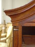
Looks pretty good.  You have a bump in there, right around the inflection point that can be cleaned up by hand, but do that before you go much further.  I also see a flat spot below the inflection point.  It looks like the registration edge needs a little fine tuning.l  As I said earlier, some areas of these mouldings are very sensitive to small errors, and this is one of them.  The opposite may be said of the usual requirement to carve the joins between straight and curved sections after assembly.  The adjustments will have to be feathered back away from the joint a couple of inches at most, but the human eye forces the perception that the profile is the same along the length of the moulding.  I try to make most of the adjustments to the curved mould rather than the straight parts.  The eye quickly perceives bumps, but much less so a gradual, small change of profile along the length of a moulding, especially a curved one.  This latter condition is what many of us will end up with after the mouldings are installed.

You should also bear in mind that many of the other posters here know a great deal more than I, and have done this many times.  I've done it only a few times, but never the same way twice (I think).  Do you have the drawings for this feature that I posted on this site a couple of months back?  They show the drawing centers of a John Townsend chest on chest, as measured by me.  I can send you these by email if you like, if I haven't already.  There are three centers to locate.  The first two centers are for the gooseneck, the third is for the radius moulding.  Starting from the outside edge of the case, the first center is used for the lower half of the gooseneck, and is located directly, or almost so, above the outside edge of the moulding.  In this way the lower portion of the moulding goes level just as it terminates, which I believe was the idea behind it.  The second center is for the upper portion of the gooseneck, and is controlled by the starting and stopping points of the upper edge of the moulding, where it goes level.  The drawing should help, because I can't explain it well here.  I won't try to articulate the location principle of the radius mould center, but the drawing should reveal it.

It's been a while since I thought about the geometry of it, but you reminded me that, with respect to the line formed by the upper edge of the moudling,  the radius of the upper gooseneck is necessarily different from that of the lower part.  Also, for any given radial cross-section, each line will be made with a different radius than its neighbors.  This may seem an academic point, but if you derive or know the principles of this layout, you can lay them out simply with drafting tools for any case width and desired bonnet height.  Townsend's bonnets rise a third of the case width.  Most other Newport pieces rise a good deal more, but my theory allows for any rise in the bonnet you'd like.

I honestly believe that we're looking at something close to sacred geometry here.

JD
 
A Bridgeport is a milling machine used for metal working.  The table moves in 0.001" increments in an X,Y,Z plane.  It's like a overhead router set up.

Dennis Bork
 
JD,
When I roughed out the blank on the bridgeport, I put the bottom of the molding against the "fence."  Al suggested when routing to always keep the fence on the waste side, so that's what I was doing.  I use the top edge of the moling as a reference with the scratch stock, so the difference between the two is a little exaggerated I think.  My plan is to get all the bugs out with this piece, figure out if it will work with my straight stock, then make two good moldings using this one as a template. 
Rob
 
Back
Top